Spanish
 Arabic
 French
 Portuguese
 Belarusian
 Japanese
 Russian
 Malay
Malay Icelandic
 Bulgarian
 Azerbaijani
 Estonian
 Irish
Irish Polish
 Persian
 Boolean
 Danish
 German
 Filipino
 Finnish
 Korean
 Dutch
Dutch Galician
 Catalan
 Czech
Czech Croatian
 Latin
Latin Latvian
 Romanian
 Maltese
 Macedonian
 Norwegian
 Swedish
 Serbian
 Slovak
 Slovenian
 Swahili
 Thai
Thai Turkish
 Welsh
Welsh Urdu
Urdu Ukrainian
 Greek
Greek Hungarian
 Italian
 Yiddish
 Indonesian
 Vietnamese
 Haitian Creole
 Spanish Basque


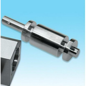
The above is a structural diagram of the spindle components of a vertical CNC Machining center. It consists of an automatic clamping and releasing mechanism for the spindle and cutting tools, as well as front and rear bearings. The front end of the spindle adopts a 7:24 taper hole, which is easy to install and remove the tool holder, and has a critical friction torque. The standard pull nail 5 is tightened inside the tool holder.
When it is necessary to tighten the tool, there is no oil pressure in the upper oil chamber of piston 1, and the spring force of the stacked spring 3 moves piston 1 upward to the position shown in the diagram. Pull rod 2 moves upward to the position shown in the diagram under the pressure of spring 3, and steel ball 4 is forced to retract and clamp in the ring groove of pull pin 5. Pull pin 5 is tightened upward through the steel ball pull rod, so that the outer cone surface of the tool holder cone and the inner cone surface of the spindle cone hole are mutually compressed, and the tool holder is clamped on the spindle.
When the handle is relaxed, hydraulic oil enters the upper oil chamber of piston 1, and the oil pressure causes piston 1 to move downwards, pushing rod 2 to move downwards. At this point, the stacked spring 3 is compressed, and the steel ball 4 moves downward along with the tension pin 5. When the steel ball moves to a larger spindle aperture, the tension pin 5 is released, and the tool and tension pin 5 can be removed by the robotic arm. After the robotic arm installs the new tool handle, the hydraulic oil in the oil chamber of piston 1 releases pressure and tightens the tool handle.
The handle clamping mechanism uses spring clamping and hydraulic relaxation to ensure that in the event of a sudden power outage during operation, the handle will not loosen on its own.? There is compressed air connected to the upper end of the piston rod hole. When the robotic arm extracts the tool from the spindle, the compressed air blows the spindle taper hole through the center hole of the piston rod and pull rod, making the taper surface of the tool holder tightly fit with the spindle taper hole, ensuring the correct positioning of the tool. Travel switches 7 and 8 are used to send signals for clamping and loosening the tool holder.