Spanish
 Arabic
 French
 Portuguese
 Belarusian
 Japanese
 Russian
 Malay
Malay Icelandic
 Bulgarian
 Azerbaijani
 Estonian
 Irish
Irish Polish
 Persian
 Boolean
 Danish
 German
 Filipino
 Finnish
 Korean
 Dutch
Dutch Galician
 Catalan
 Czech
Czech Croatian
 Latin
Latin Latvian
 Romanian
 Maltese
 Macedonian
 Norwegian
 Swedish
 Serbian
 Slovak
 Slovenian
 Swahili
 Thai
Thai Turkish
 Welsh
Welsh Urdu
Urdu Ukrainian
 Greek
Greek Hungarian
 Italian
 Yiddish
 Indonesian
 Vietnamese
 Haitian Creole
 Spanish Basque


CNC milling significantly improves cutting efficiency and tool life
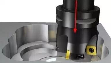
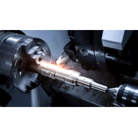
The significant progress made in improving metal cutting efficiency is the result of the joint efforts of tool manufacturers, machine tool manufacturers, and software developers. Insertion milling (Z-axis milling) is a good example of machining. During insertion milling, the rotating tool directly cuts into the workpiece along the Z-axis direction and retracts the tool upwards along the Z-axis. Then, it moves horizontally along the X-axis or Y-axis direction for a certain distance, and performs vertical cutting that overlaps with the previous cutting part to cut more workpiece material. Insertion milling has many benefits. Especially in long overhang machining (such as milling deep mold cavities), the traditional flat milling method (i.e. milling from one side of the workpiece to the other) has to reduce the cutting speed in order to minimize the lateral force that can cause chatter. During insertion milling, the cutting force is directly transmitted to the machine spindle and worktable, thus achieving a much higher metal removal rate than traditional milling methods. According to AMT Software Company, the Prospector CAM software package developed by the company includes the insertion milling function. Compared with traditional flat rough milling using button shaped milling cutters, the metal removal rate of insertion milling processing can be improved by at least 50%. Due to its ability to minimize the lateral load on machine tool components, slot milling can be used for old-fashioned or lightweight machine tools with insufficient rigidity to improve productivity. John Ross, the marketing manager of Doushan Machine Tool Company, agrees with the statement that slot milling can reduce the cutting force acting on low performance machine tools, but he adds that in new machine tools with structural design that is conducive to slot milling processing, the advantages of this process can be maximized. He pointed out that due to the direct transmission of milling cutting force into the machine tool spindle and worktable, various problems caused by weak workpiece clamping can be minimized to the greatest extent. Bill Fiorenza, Product Manager of Ingersoll Tool Company's Mold Production Line, stated that insert milling helps reduce cutting heat entering the tool and workpiece. He said, "During insertion milling, there is not much heat entering the workpiece because the cutting tool rotates at a fast speed to cut in and out the workpiece. Only a small portion of the workpiece with a moving step makes contact with the tool." This feature is particularly advantageous when cutting difficult to machine materials such as stainless steel, high-temperature alloys, and titanium alloys. Fiorenza explained during the insertion and milling demonstration, "Usually, the temperature of metal chips is very high, and you can even bake a sandwich in the chip pile. However, when the insertion and milling process is completed, you can immediately place your hand on the workpiece and feel cooler to the touch." Reducing cutting heat can not only extend the tool life, but also minimize the deformation of the workpiece.
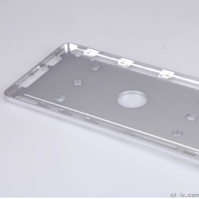
【 Worth a try 】 Insertion milling can greatly accelerate the production rhythm of high-end and complex components. Gary Meyers, milling product manager at Seco Tool Company, stated that "the most commonly used areas of insert milling technology are mold manufacturing and aviation industry, as the types of parts in these industries are very suitable for insert milling." Mold manufacturers need to mill various complex shapes on the overall workpiece to form mold cavities, and many aviation parts are also processed from whole blanks. He said, "The cutting amount of these workpieces is astonishing, and in some cases, it is necessary to cut 50% -60% or even more of the workpiece material from the blank." Kenyon Whetsell, Product Manager of DP Technology, the developer of ESPRIT CAM software, pointed out that in addition to manufacturers of complex parts, general-purpose machining workshops can also benefit from the application of insert milling technology. Metal processing WeChat, the content is good and worth following. He said, "Some workshops are still using 2.5-axis machining technology, which has outdated machine tool types, poor rigidity, and insufficient clamping force of fixtures. However, they still hope to improve productivity. These workshops can use 2.5-axis milling technology to achieve this goal." Juan Seculi, Global Product Manager of Kenner's Indexable Milling cutters, believes that "milling technology is widely applicable to complex shapes and cavities of large and medium-sized parts. In this type of machining, the length to diameter ratio of the milling cutter is crucial, and traditional milling strategies can generate chatter and vibration, shortening tool life. Kenner recently rebuilt its Z-axis milling cutter sales platform to meet the growing demand of users." The demand for. "Time has proven that the sales volume of Z-axis milling cutters is constantly increasing, with an annual growth rate of 40%."
The design characteristics of milling cutters: Tool manufacturers have developed various milling cutters that can fully leverage the advantages of milling technology. Meyers from Shangao Tools said that the cutting force of such tools is basically directly transmitted back to the Z-axis. The geometric shape of the insert milling cutter is very similar to that of the 90 square shoulder milling cutter. The difference lies in the deviation of the leading angle of the milling blade from the vertical plane by a few degrees, which may be 87 instead of 90. If a 90 ° milling cutter is used to insert and mill the sidewall downwards, the entire cutting edge of the blade will rub against the sidewall. If the leading angle of the tool is 87, there is a gap between the cutting edge and the workpiece sidewall. The milling cutter should use the cutting edge at the bottom of the blade to avoid cutting from the blade side, as the transition from the bottom to the side is the weakest point of the blade, and machining from the blade side may cause radial cutting forces that can cause vibration. Meyers added that although cutting with the side of the blade is not common, in some machining processes called "up (or down) profile milling", the milling cutter can insert and mill complex shapes in the up and down strokes. A simple example is to use the bottom root cutting method to mill straight sidewalls. "You can first insert milling downwards, then move inward, and mill the root of the workpiece." Meyers believes that the limitation of insert milling technology is the difference between the actual cutting diameter of the tool and the diameter of the tool body. In order to provide maximum support to the cutting edge, the body of the standard face milling cutter needs to be enlarged to be as close as possible to the entire cutting diameter of the tool. For the slot milling cutter used for profile milling, the cutting diameter of the blade exceeds the diameter of the tool body. Metal processing WeChat, the content is good and worth following. He said, "But there is a certain limit to the amount exceeded, because the extension of the milling blade cannot be too large." Meyers said that although milling is a typical rough milling process, its technology and tools are also suitable for semi precision and precision machining. He suggested that in order to achieve better machining surface smoothness, the radial cutting step should be reduced, which is the same as the reduced step machining method used in 3D precision milling with ball end mills. Meyers explained that fundamentally, the cutting step distance is determined based on the width of the blade and the amount of material cut into the workpiece by the cutting edge. The recommended step size for tool product samples will result in a certain residual height, which determines the surface roughness of a specific insert milling cutter.
Seculi from Kenneth Metal stated that the design of the milling cutter is constantly being improved and perfected. For example, the new features of the Kenner Z-axis milling cutter include: the serrated structure designed on the cutter body can improve chip formation and chip removal performance, and the design of the coolant outlet can improve the control of cutting heat and chip removal performance. He said, "These integrated structural designs with the tool body, combined with the use of a large rake angle rake face, can reduce cutting force, lower the demand for machine tool power, thereby extending tool life and improving machining reliability."
Fiorenza pointed out that although the application of CAM milling technology has a history of at least 15 years, in recent years, machining workshops have become increasingly aware that milling can achieve higher material removal rates, and due to easier programming and verification of tool paths, the application of milling has become easier than in the past. More and more CAM systems have algorithms specifically designed for insertion and milling machining. In addition, using cutting simulation software, the machining workshop can verify its reliability before running the milling cycle program. Fiorenza said, "You do need to verify the motion of the tool along the cutting path, because specialized milling cutters are usually not center cutting tools." When using non center cutting tools, if the selected cutting step is not appropriate or the machining allowance of the workpiece is unclear, it is possible to cause cutting. According to Meyers, some workshops use the G81 drilling cycle program in CNC Machining to perform milling operations. But in this type of machining, when the milling cutter returns from downward insertion, its blade may scrape against the side wall of the workpiece. To solve this problem, a specially designed CAM milling cycle program moves the tool 0.025-0.050mm along the X-axis or Y-axis direction before it reaches the bottom of the insertion and prepares to retract back to its travel vertex. Moving the tool backward can avoid scratching between the blade and the machined surface during tool retraction. Meyers said, "It is also possible to manually program the insertion and milling cycle. In some cases, if it is a simple insertion and milling with the same insertion depth, you can only write one subroutine to determine the movement of the tool in the X or Y axis. However, manual programming is a lot of work and should only be used when it is necessary and not necessary to write machining code." Whitsell from DP Technology said, "We try to optimize the insertion and milling machining cycle, so that users can fully tap into the maximum potential of the insertion and milling cutter in each cutting, with as few tool passes as possible, and cut as many workpiece materials as possible. When determining programming parameters, it is necessary to dynamically adjust the axial feed of the tool into the workpiece. The purpose of calculation is to maximize the cutting ability of the blade in each milling operation. This requires knowing the dimensions of the workpiece blank and the finished parts after processing As long as the final size of the part is known, the milling depth of the milling cutter can be determined, and knowing the size of the workpiece blank can determine where to start milling. Metal processing WeChat, the content is good and worth following. Whetsell said, "This is basically the programming information for workpieces that have been previously processed by insert milling at the current stage. In DP's ESPRIT CAM software, we refer to it as' automatic programming of workpieces'." Whetsell said, "Programming the backward cutting tool in the X or Y axis direction becomes a bit tricky because you can't let the tool just retreat into the subsequent workpiece material, and you don't want to retreat the tool into the residual material generated by the previous cutting." CAM software can program insert milling in various different ways. Whetsell said, "For example, you can define the residual height (such as 0.25mm) without defining the cutting step or radial cutting width, and CAM software can calculate the number of milling operations to achieve that residual height." DP Technology is developing a dedicated milling cycle for ESPRIT software, and some users have already developed milling programs through the advanced programming interface of the software package. According to Seculi from Kenner Company, the cutting parameters and professional terminology used in slot milling are different from other milling methods. For example, to prevent vibration, a lower cutting speed should be used when the milling cutter overhangs for a long time. When describing the insertion milling process, the meaning of Ap used to represent the axial cutting depth in planar milling has also changed, as it is positioned radially on the insertion milling cutter rather than in the vertical axis direction. In Z-axis milling, there is no axial cutting depth dimension, only radial cutting depth (i.e. cutting step distance) and radial cutting size. The cutting depth is usually related to the size of the blade. Kenner Company suggests that during insertion milling, the cutting depth should always be maintained to be greater than 15% of the cutting length of the blade. If the cutting depth becomes close to or less than the radius value of the tool tip arc of the blade, the radial cutting force will increase, thereby losing some advantages of the insertion milling technology.
Insertion milling and high feed milling are metal cutting strategies with high productivity. The choice between using this technology or other milling strategies depends on multiple factors. In order to maximize the advantages of milling, it is necessary to use specialized milling cutters and carefully carry out CAM programming. In many cases, high feed milling can become a simpler and more feasible alternative to slot milling, and high feed milling cutters are basically straight edge milling cutters with large lead angles. A large lead angle thins the chips, and in order to maintain sufficient chip thickness, it is necessary to increase the feed rate. High feed milling cutters can quickly cut metal materials with high feed rates and small cutting depths, while minimizing the lateral load acting on the machine tool and cutting tools. Tom Noble, MAXline Product Manager at Ingersoll Tools, believes that the characteristic dimensions and structure of the parts can help the machining workshop decide whether to use insert milling or high feed milling. He said, "If a small concave cavity needs to be machined, using insert milling may be more suitable. Due to the short radial movement distance, there is no need to mill too much material radially. However, if the area to be milled is quite large, using high feed milling may be more efficient." High feed milling does indeed have lateral loads, but it can be minimized by using small cutting depth, fast feed, and multiple tool passes. Fiorenza of the company pointed out that using a milling cutter with a diameter of 50mm or more for long overhang milling may be very effective. High feed milling may be more suitable for long overhang milling with small diameter milling cutters. He said, "When the overhanging length of the cutting tool increases to 4 or 6 times the diameter, certain types of chatter will begin to occur. You can use high feed milling cutters and small cutting depths of 0.38-0.50mm to cope with these processing. You may also need to use some anti vibration tool structures, such as integral hard alloy tool holders and modular tool heads." Noble believes that a key factor in choosing a milling method is the daily machining tasks in the workshop. "For example, if you want to perform a large amount of 3D milling in your daily life and also want to do some insert milling, I would recommend using high feed milling cutters, which can also perform limited insert milling. But for cavity milling,... For milling, straight wall and groove milling, as well as large-scale processing, you should invest in purchasing specialized slot milling cutters
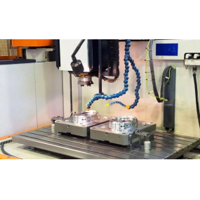
Although general-purpose machine tools have the advantage of being versatile, using specialized machine tools is often a better choice in order to maximize productivity (and reduce deformation). Doushan Machine Tool Company, which produces products such as vertical machining centers (VMCs) and horizontal boring and milling machines, can provide various types of machine tools from lightweight tapping centers to high-speed five axis machining centers for heavy-duty cutting of molds. Metal processing WeChat, the content is good and worth following. Marketing Manager John Ross stated that the company can customize machine tools for different processing (and even different regions). For example, some machine tools use linear guides, while others use more sturdy hard rails. When we enter the market in some parts of California, USA, which mainly cuts light materials, linear guide rail machine tools are on the right track. However, when we enter the market in the Midwest, which processes aviation materials and high-temperature alloys, users need hard rail machine tools that can withstand larger cutting forces and are more durable and durable. High speed mold processing machines using linear guide rails have excellent performance in quickly cutting small amounts of workpiece materials, and using insert milling technology can further improve their rough machining ability. But the ability of this type of machine tool to withstand chip load is not as good as that of hard rail machine tools. Ross pointed out that the Mynx series vertical machining centers of Doosan are the machining platforms that can maximize the advantages of insertion milling, and their rigidity is the highest among Doosan VMCs. The base of the machine tool is made of integral casting, and the 1500mm750mm worktable can process large molds or aviation castings. Steve Sigg, an application engineer at Doushan Company, pointed out that "the thicker the spindle of a machine tool, the stronger the milling ability." In heavy-duty cutting, slot milling technology can help users efficiently rough mill some difficult to machine materials (such as Inconel alloy and stainless steel), while using a face milling cutter for radial machining of these materials is very inefficient. When the tool overhang is large, the lateral milling force can cause excessive vibration, and slot milling can also effectively solve this problem. He also mentioned that another reason why manufacturers have become interested in plug milling is that with the revival of American manufacturing, some mold processing tasks are constantly returning from China to the United States.