Spanish
 Arabic
 French
 Portuguese
 Belarusian
 Japanese
 Russian
 Malay
Malay Icelandic
 Bulgarian
 Azerbaijani
 Estonian
 Irish
Irish Polish
 Persian
 Boolean
 Danish
 German
 Filipino
 Finnish
 Korean
 Dutch
Dutch Galician
 Catalan
 Czech
Czech Croatian
 Latin
Latin Latvian
 Romanian
 Maltese
 Macedonian
 Norwegian
 Swedish
 Serbian
 Slovak
 Slovenian
 Swahili
 Thai
Thai Turkish
 Welsh
Welsh Urdu
Urdu Ukrainian
 Greek
Greek Hungarian
 Italian
 Yiddish
 Indonesian
 Vietnamese
 Haitian Creole
 Spanish Basque

Flanges are fundamental components in mechanical engineering and pipeline installation, serving as raised collars or rims that join two elements together. They permit sealed connections through bolting and welding, providing safety from leakages while enduring pressure, temperature, and mechanical loads. This article provides a detailed analysis of flange types, connection methods, and CNC Machining techniques, with insights from EMAR’s precision manufacturing experience.
What Is a Flange?
A flange is a flat, circular object used to join two components together. Their common uses are in pipes, valves, pumps, and machinery. Flanges allow for the connecting and disconnecting of components while helping create airtight seals between them. A flange can bear high pressure, temperature, and mechanical loads, typically featuring bolt holes around the perimeter for attachment. They are normally made of steel and stainless steel, depending on the intended use.
In simple terms, a flange is an annular part used to connect pipes, valves, pumps, and other equipment. It is usually fitted with bolt holes that enable tight connections using fasteners such as bolts and nuts. The presence of flanges ensures that complex mechanical systems work both stably and efficiently.
How Does a Flange Connection Work?
1. Design
Flanges are circular plates with a flat face and bolt holes around their periphery. They are intended to join pipes, valves, and other equipment securely. The design provides correct orientation and a rigid kinematic joint, with smooth and raised surfaces normally used to improve the sealing mechanism.
2. Bolting
Flanges are fastened by using bolts that run through holes provided on both sides. When the bolts are tightened, the two flanges come into contact and compress the gasket in between, creating a well-fitted, watertight, or air-tight seal.
3. Gaskets
To ensure no leaks between the two flanges, a gasket is always inserted in between. Gaskets remain flexible when screwed on and shrink to form a compact seal. They also reduce vibrations and allow for small misalignments.
4. Pressure and Temperature Rating
Every seal connection is intended for certain pressure and temperature requirements, defined by the design and material. The flange must be chosen correctly for the system to avoid failures.
5. Installation
A flange connection is physically brought into alignment first. Then a gasket is fitted between them before they are bolted. Bolts must be well-tightened to achieve a good connection with no leakage. Excessive or inadequate installation can lead to leakage or harm to internal surfaces.
6. Maintenance
Flange connections require frequent patrolling of gaskets for signs of wear, rusting, or leakage. This is essential for dependable connections in high-pressure or high-temperature systems.
Sealing Mechanism
Flange connection leakages mainly occur through two paths: gasket leakage (fluid passing through capillaries in the gasket material) and contact surface leakage (at the interface between gasket and flange). Micro-unevenness on the flange surface arises from mechanical deformation and vibrations during machining, which needs to be filled with a semi-plastic gasket to avoid fluid leakage.
Typical Types of Flanges
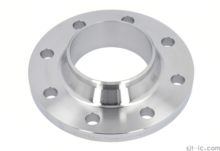
1. Weld Neck Flange
Welders attach a weld-neck flange to the pipe using a long tapered hub. These offer a firm and long-lasting joint for high pressures and temperatures. Their conical shape distributes stresses and ensures no leakage occurs.
2. Slip-On Flange
Engineers slip slip-on flanges over the pipe, then weld their face as well as the pipe. These are comparatively cheaper and easier to install, recommended for low-pressure systems.
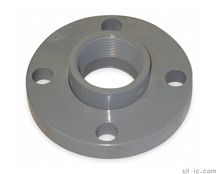
3. Threaded Flange
Threaded flanges have internal and external threads that match the threads of a pipe. Workers fix them by screwing, avoiding the use of welding. They are widely applicable for low-pressure systems.
4. Lap Joint Flange
Lap joint flanges are accompanied by loose backing. The pipe ends slip into the lap joint, and workers screw the lap joint flange to its backing.
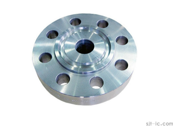
5. Ring-Type Joint (RTJ) Flange
RTJ features a groove where a metal ring gasket is placed to create a high-pressure seal. Commonly applied in oil and gas industries where pressures and temperatures are relatively high, they guarantee a leakage-proof connection.
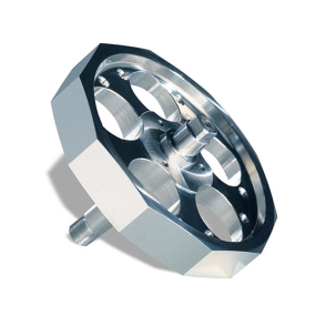
6. Orifice Flange
Orifice flanges are meant to be fitted with a flow meter or an orifice plate within pipeline systems. They have ports for determining the flow rate of fluids or gases and hold integral pressure ports for pressure measurements.
7. Van Stone Flange
Van Stone flanges have a beveled edge providing a tight and leakproof interface. They are well applicable for low to medium-pressure applications and provide ease of installation.
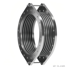
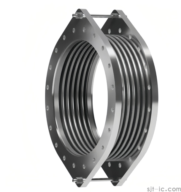
8. Tied Flange
Tied flanges are used in pressure vessels operating at high pressure and temperature. They have a tie bar that joins their outer diameter to ensure no separation under extreme pressure conditions.
9. Flat Face Flange
Flat face flanges have a flat sealing surface, featuring a simple structure and ease of machining. Suitable for applications with low pressure and non-toxic media, sealing is mainly achieved through gaskets between the flanges.
10. Blind Flange
Blind flanges serve as solid covers to seal pipe ends, vessels, or testing points. They are essential for system isolation during maintenance, pressure testing, future expansion points, and emergency shutoffs.
Different Faces of a Flange to Connect
Male and Female (M&F) Faces: One flange has a bulge (male) and the other has an indentation (female), creating a perfect fit common in pipelines and high mechanical applications.
Tongue and Groove (T&G): A protruding “tongue” on one flange and a matching groove on the other, offering better grip and less risk of separation or leakage.
Flat Face with Raised Face (FF-RF): A flat face with a sealing area over it. Seals better in systems with limited space and special sealing requirements.
Recessed Face (RF): A groove surrounding the sealing area that retains the gasket, commonly used for improved sealing in high-pressure applications.
Integral Flange (IF): A pipe fitting made in one piece, with the flange and pipe manufactured simultaneously, making the connection easier and reducing leakage.
Flange Dimensions and Considerations
Nominal Pipe Size (NPS): Defines essential flange dimensions, generally ranging from ½ inch (DN 15) to 24 inches (DN 600).
Bolt Circle Diameter (BCD): Depends on flange size (e.g., for 1 NPS, BCD is around 2.75 inches).
Bolt Hole Size: Usually drilled to bolt diameter plus 1/8 inch.
Flange Face Type: Flat Face (up to 150 psi), Raised Face (600 or 1500 psi), Ring-Type Joint (above 1500 psi).
Thickness: Depends on pressure class and material. Example: 150 lb flanges approximate 0.25 inch for small NPS.
Pressure Rating: Class 150 (up to 285 psi), Class 300 (up to 740 psi), Class 600 (up to 1480 psi), Class 1500 (up to 3700 psi).
Gasket Compatibility: Flat gaskets for flat face flanges, ring gaskets for RTJ flanges, spiral wound gaskets for raised face flanges up to 3000 psi.
Standards and Codes: ASME B16.5 (1/2" to 24"), ASME B16.47 (26" and larger), API 6A (oil and gas, up to 20,000 psi).
End Connections: Welded, Threaded (up to 2½ inches), Slip-On (up to 24 inches).
Machining Techniques of Flanges
CNC Turning
CNC turning peels material away from a revolving workpiece, forming a cylindrical shape with a cutting tool. This minimizes rough surfaces and helps create accurate dimensions. Turning is best for flanges with close tolerances (e.g., ±0.01mm), such as weld neck high-pressure flanges.
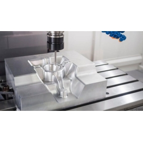
CNC Milling & Drilling
CNC milling employs revolving cutting tools to carve off material, creating flat, angular, contoured, and other surface types. Milling is optimal for designing seal edges and intricate shapes. CNC drilling helps make bolt holes with precise hole position accuracy.
Tapping
Tapping involves cutting internal threads into holes, shaping flanges ready for bolts and fasteners while securing the right thread size.
CNC Grinding
Grinding rubs a surface against an abrasive wheel, offering a smooth finish to flange faces. It helps achieve high accuracy levels for sealing surfaces and their fitness.
Face Milling
Face milling removes material from the flange surface to form a plane, uniform surface for sealing, providing proper gasket installation and functionality.
CNC Grooving
Grooving cuts narrow grooves into the flange, frequently forming an area for gaskets or seals. This prevents incorrect gasket positions during operation.
Cutting/Shearing
Manufacturers create flange blanks from metal profiles by cutting shapes. Shearing requires high force and puts the flange in condition for further machining processes.
Blasting
Cleaning flange surfaces using abrasives removes rust and unwanted materials, providing a sleek, clean aesthetic shape and making the flange ready for final turning or painting.
CNC Welding
The welding process joins two or more metal parts through heat or pressure, providing firm and irreversible links.
Flange Machining Process Steps
Material Selection
The operating environment determines material choice: carbon steel for general applications, stainless steel for corrosion resistance, alloy steel for high pressure and temperature, cast iron for lower-pressure systems, and duplex stainless steel for harsh environments.
Forging or Casting
Forged flanges have higher mechanical performance and better structural density, while cast flanges can be used for more complicated shapes and sizes.
Heat Treatment
Flange blanks undergo heat treatment (annealing, normalizing, quenching, and tempering) to remove internal stresses, improve structural performance, and increase mechanical strength.
Flange Machining
Precise machining using lathes, milling machines, drilling machines, and other equipment focuses on dimensional accuracy and surface quality. Tool selection, cutting parameter setting, and processing sequence are critical.
Surface Treatment
Anti-rust coatings, painting, or other surface treatments improve corrosion resistance and appearance.
Inspection and Packaging
Finished flanges undergo rigid inspection for dimensional accuracy, surface quality, and mechanical performance before packaging and storage.
Example: Machining a DN100 Flange on a Machining Center
For processing a standard DN100 flange (center hole 108mm, outer diameter 215mm, thickness 24mm, 8×φ18mm bolt holes), EMAR engineers recommend a machining center with X, Y, Z axis travel of 800*450*500mm, spindle taper BT40, and a fourth axis (indexing plate) for sub-processing bolt holes in one clamping.
Simple Process for DN100 Flange:
1. Preparation:
Confirm flange standard (GB/T 9119-2010), dimensions, material (Q235, 304 stainless steel), and processing requirements.
Select round steel or flange blanks (e.g., φ230mm round steel).
Prepare end mills, drills, boring tools, chamfering tools.
Use a vise or special fixture for stable clamping.
2. Processing:
Clamp workpiece and set tool coordinate system (G54).
Rough machining: Mill outer circle to ≈222mm (leave 0.5mm finishing allowance), mill end faces flat, rough inner hole to ≈102mm.
Fine machining: Fine mill outer circle to φ220mm, bore inner hole to φ110mm.
Bolt hole machining: Use center drill to locate and drill 8×φ18mm bolt holes evenly distributed on φ180mm circumference.
Chamfer inner and outer edges C1-C2 (45°) and deburr bolt hole mouths.
3. Notes:
Thin flanges need light pressing or equal height blocks to avoid milling deformation.
Stainless steel materials require reduced speed and regular tool checks.
Run first piece in single-stage mode, then perform batch processing after confirmation.
Quality Control in Flange Manufacturing
Material verification: Chemical composition testing, physical properties validation, heat treatment certification, material traceability.
Dimensional inspection: Advanced CMM measurements, surface finish verification, roundness and flatness checks, bolt hole alignment validation.
Non-destructive testing: Magnetic particle inspection, ultrasonic testing, dye penetrant examination, radiographic inspection when required.
Choosing the Right Flange Machining Method
Turning: Best for round flanges with close tolerances. Use CNC lathes for large lots to improve efficiency.
Milling: For complex geometries like grooves, keyways, or non-circular holes. CNC milling machines support complex geometries with surface roughness up to Ra 3.2μm.
Drilling: Specialized for bolt holes. CNC drilling machines provide precise hole diameter and position.
Grinding: For high-precision sealing surfaces with low roughness and high flatness. Best for hard materials or heat-treated flanges.
Post-Forging Machining: For forged flanges with high strength, using rough and finish machining to achieve design dimensions.
Post-Casting Machining: Processes cast flanges to improve rough surfaces, with non-destructive testing to adjust for potential porosity.
Conclusion
Flanges play the key role of providing easy, reliable, and leakproof joints between pipes, valves, and other system components. Basic machining operations including turning, milling, drilling, and welding are crucial for producing desired accuracy and standard quality. Face milling, grooving, tapping, and other processes further improve flange functionality and performance.
At EMAR, we focus on providing quality, accuracy, and customized flanges that fit customer requirements. Our advanced manufacturing technologies and zero tolerance for compromise on quality enable us to deliver optimal quality flanges. For any important pipelines or intricate equipment, you can turn to EMAR for highly efficient and long-lasting flanges.
Contact EMAR Today:
Phone: +86 18664342076
Email: sales8@sjt-ic.com
FAQs
What materials are ideal for making flanges?
Carbon steel for general applications, stainless steel for corrosion resistance, alloy steel for high pressure and temperature, cast iron for lower-pressure systems, duplex stainless steel for harsh environments, titanium for aerospace, and copper alloys for marine applications.
What are the specifications of flanges?
Specifications include Nominal Pipe Size (NPS), pressure ratings (Class 150, 300, etc.), flange type (weld neck, slip-on, blind), material, flange face (flat, raised, RTJ), bolt hole pattern, thickness, and industry standards.
When is it best to use a flange fitting?
Flange fittings are ideal for high-pressure, high-temperature, or corrosive environments. They are best used when frequent disassembly is needed for maintenance or inspection, offering easy detachment without compromising system integrity.