Spanish
 Arabic
 French
 Portuguese
 Belarusian
 Japanese
 Russian
 Malay
Malay Icelandic
 Bulgarian
 Azerbaijani
 Estonian
 Irish
Irish Polish
 Persian
 Boolean
 Danish
 German
 Filipino
 Finnish
 Korean
 Dutch
Dutch Galician
 Catalan
 Czech
Czech Croatian
 Latin
Latin Latvian
 Romanian
 Maltese
 Macedonian
 Norwegian
 Swedish
 Serbian
 Slovak
 Slovenian
 Swahili
 Thai
Thai Turkish
 Welsh
Welsh Urdu
Urdu Ukrainian
 Greek
Greek Hungarian
 Italian
 Yiddish
 Indonesian
 Vietnamese
 Haitian Creole
 Spanish Basque

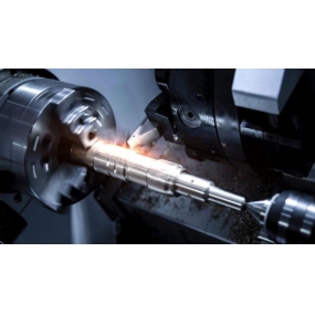
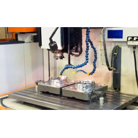
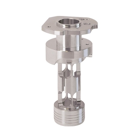
Hardware stamping parts processing factory, processing various hardware stamping parts, stainless steel stamping parts. Mechanical components, etc. Before processing Metal Stamping parts, it is necessary to plan the matching molds. Mold part drawings require professional personnel to plan and draw. Let's take a look at the requirements for making metal stamping mold part drawings?
1. The view of the metal stamping mold part drawing should be correct and sufficient: the selected view should fully and accurately indicate the internal and external structural shape and scale size of the part, and the number of views should be minimized.
2. The graphics need to be complete: The purpose of drawing a stamping die part diagram is to reflect the structure of the part and provide illustrations for processing the part. All non-standard parts or parts that are standard but still require further processing must have part drawings made. Although some parts are standard components, they still need to be machined with leakage holes, screw through holes, and pin holes, so it is necessary to draw stamping mold part drawings. Parts such as guide columns, guide sleeves, and screw pins are standard components and do not require further processing, so part drawings can be omitted. The view of the metal stamping mold part drawing should be placed correctly: to ensure the correctness of the part drawing, it is recommended to draw the part drawing according to the installation orientation, while for shaft parts, the part drawing should be drawn according to the machining orientation (usually the axis line is horizontally placed). The front view of the component on the installation diagram reflects the structure in the thickness direction, while the top view shows the structure in the original plane.
4. The marking scale should be correct: all cooperative scales and scales with high accuracy requirements should be marked with tolerances. The dimensions that need to be processed during the installation process of metal stamping mold parts should be marked on the installation drawing. If it is necessary to mark them on the part drawing, they should be marked near the relevant dimensions. When a certain installation allowance is required for installation, the installation chain compensation amount and the required cooperation scale, tolerance, and surface roughness after installation can be marked on the part drawing.
5. To meet the corresponding skill requirements: Any conditions and requirements that are not easily indicated in symbols or drawings, but are necessary to ensure during production, should be specified in the skill conditions, and their content should vary depending on the different metal stamping parts, requirements, and processing methods.
This article is from EMAR Mold Co., Ltd. For more EMAR related information, please click on www.sjt-ic.com,