
How to Process Aluminum Cylinder Liner with CNC: A Practical Guide
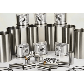
Aluminum cylinder liners are important engine parts that require high precision, good surface quality, and strong durability. Many industries, especially automotive and industrial equipment manufacturers, use CNC Machining to produce aluminum cylinder liners because CNC machines can achieve accurate dimensions and stable production quality.
If you want to know How to process aluminum cylinder liner with CNC, this guide explains the complete process, including material preparation, tool selection, CNC parameter setting, machining steps, and quality inspection. It also provides practical advice for achieving reliable results and reducing production costs.
Why Use CNC Processing for Aluminum Cylinder Liners?
Aluminum cylinder liners have strict requirements because they directly affect engine performance, heat transfer, and service life. Traditional machining methods may struggle to maintain consistent accuracy, especially for complex internal surfaces.
CNC machining provides several advantages:
- High dimensional accuracy for cylinder diameter and roundness.
- Stable production quality for small and large batches.
- Better surface finish to reduce friction between parts.
- Flexible processing for different aluminum alloy materials and designs.
- Lower human error through automatic machining programs.
For companies requiring CNC processing of aluminum cylinder liner for automotive engines, CNC technology helps achieve the precision needed for modern engine systems.
Step-by-Step Process of CNC Processing Aluminum Cylinder Liners
Step 1: Select the Right Aluminum Material
The first step is choosing suitable aluminum alloy materials. Different applications require different material properties.
Common aluminum alloys used for cylinder liners include:
- Aluminum alloy 6061: Good strength, easy machining, and suitable for many industrial applications.
- Aluminum alloy 7075: Higher strength and often used for demanding applications.
- Aluminum-silicon alloys: Commonly used in engine parts because of good wear resistance and heat performance.
The material choice affects tool wear, machining speed, surface quality, and final product performance. A professional CNC machining supplier can help select the best material according to the working environment of the cylinder liner.
Step 2: Prepare the CNC Machining Drawing and Program
Before machining begins, engineers need accurate production drawings. The drawing should include:
- Outer diameter and inner diameter dimensions.
- Cylinder liner length requirements.
- Tolerance specifications.
- Surface roughness requirements.
- Special features such as grooves or mounting areas.
The CNC programmer then creates a machining program based on the drawing. Proper programming helps avoid unnecessary cutting movements and improves machining efficiency.
For How to accurately process aluminum cylinder liner with CNC, careful programming is one of the most important steps. Even a small programming error can affect cylinder performance.
Step 3: Choose Suitable CNC Tools
Tool selection directly affects machining quality. Aluminum is a soft metal, but improper tools can still cause problems such as burrs, poor surface finish, and material deformation.
Recommended tools include:
- Carbide cutting tools: Provide longer service life and stable cutting performance.
- Sharp edge milling cutters: Help reduce cutting resistance and prevent aluminum sticking.
- Special boring tools: Improve the accuracy of the inner cylinder surface.
- High-quality reamers: Used for final size adjustment and better surface finish.
Using the correct tool geometry is especially important for high-precision cylinder liner machining.
Step 4: Set CNC Machining Parameters
Correct CNC parameters help achieve both efficiency and quality. The main settings include cutting speed, feed rate, and cutting depth.
Typical considerations include:
- Cutting speed: Aluminum usually allows higher cutting speeds compared with steel, but the correct speed depends on alloy type and tool material.
- Feed rate: A proper feed rate prevents excessive tool pressure and improves surface quality.
- Cutting depth: Heavy cutting can improve efficiency during rough machining, while light cutting is better for final finishing.
A common mistake is using the same parameters for every aluminum cylinder liner. Different sizes, alloys, and designs require adjustment. Experienced machinists often test and optimize parameters before mass production.
Step 5: Perform Rough and Finish Machining
The machining process usually includes several stages:
- Rough machining: Remove extra material quickly and create the basic cylinder liner shape.
- Semi-finishing: Improve dimensions and prepare the surface for final machining.
- Finish machining: Achieve final size, tolerance, and surface quality.
- Deburring: Remove sharp edges and unwanted aluminum particles.
For Efficient CNC processing of aluminum cylinder liner, a well-planned machining sequence can reduce processing time while maintaining product quality.
Quality Control for CNC Aluminum Cylinder Liners
Quality inspection is essential because cylinder liners directly influence engine operation. A professional CNC manufacturer should check every important feature before delivery.
Key Inspection Items
- Diameter accuracy: Ensures correct fitting with the engine block.
- Roundness: Prevents uneven wear and poor sealing.
- Surface roughness: Helps reduce friction and improve lubrication performance.
- Wall thickness: Ensures strength and heat dissipation performance.
- Visual inspection: Checks for scratches, cracks, burrs, or machining defects.
Common inspection equipment includes calipers, micrometers, bore gauges, and coordinate measuring machines (CMM). These tools help verify that every part meets the required specifications.
Common Problems When CNC Machining Aluminum Cylinder Liners
1. Poor Surface Finish
Possible causes:
- Worn cutting tools.
- Incorrect cutting parameters.
- Insufficient cooling or lubrication.
Solutions: replace damaged tools, adjust machining parameters, and use suitable cutting fluids for aluminum.
2. Incorrect Cylinder Dimensions
Possible causes:
- Machine calibration problems.
- Improper tool compensation.
- Incorrect CNC programming.
Solutions: Regularly maintain CNC equipment and verify measurements during production.
3. High Production Cost
Machining costs can increase due to long processing time, excessive material waste, or frequent tool replacement.
To achieve Cost-effective CNC processing of aluminum cylinder liner, manufacturers should optimize tool paths, select suitable tools, and improve production planning.
How to Choose a Reliable CNC Aluminum Cylinder Liner Processing Supplier
Choosing the right machining partner is important for product quality and delivery reliability. Before working with a supplier, consider the following factors:
- Machining experience: Check whether the company has experience with aluminum precision parts.
- Equipment capability: Confirm that the supplier uses modern CNC machines suitable for cylinder liner production.
- Quality management: Ask about inspection processes and quality standards.
- Customization ability: Make sure the supplier can produce parts according to drawings or samples.
- Communication and support: Good technical communication reduces production mistakes.
EMAR provides professional CNC machining services for aluminum cylinder liners, supporting customized production according to customer drawings and application requirements. With experience in precision machining, EMAR focuses on stable quality, accurate processing, and efficient manufacturing solutions for different industries.
Practical Example: CNC Processing Aluminum Cylinder Liners for Engine Parts
For example, an automotive parts manufacturer may need hundreds of aluminum cylinder liners with strict inner diameter tolerance. The machining process usually starts with aluminum alloy selection, followed by CNC turning, boring, finishing, and final inspection.
By optimizing cutting tools and CNC parameters, manufacturers can improve production efficiency while maintaining consistent dimensions. This approach is widely used in High-quality CNC processing of aluminum cylinder liner for industrial applications, where reliability and long service life are important.
Final Tips for Successful CNC Processing of Aluminum Cylinder Liners
- Always start with accurate engineering drawings.
- Select aluminum-compatible cutting tools.
- Adjust CNC parameters according to material and part design.
- Perform strict quality inspections after machining.
- Work with an experienced CNC machining supplier to reduce risks.
Understanding How to process aluminum cylinder liner with CNC helps manufacturers improve product quality, control costs, and achieve stable production. With the right machining methods and professional support, aluminum cylinder liners can meet demanding automotive and industrial requirements.