Spanish
 Arabic
 French
 Portuguese
 Belarusian
 Japanese
 Russian
 Malay
Malay Icelandic
 Bulgarian
 Azerbaijani
 Estonian
 Irish
Irish Polish
 Persian
 Boolean
 Danish
 German
 Filipino
 Finnish
 Korean
 Dutch
Dutch Galician
 Catalan
 Czech
Czech Croatian
 Latin
Latin Latvian
 Romanian
 Maltese
 Macedonian
 Norwegian
 Swedish
 Serbian
 Slovak
 Slovenian
 Swahili
 Thai
Thai Turkish
 Welsh
Welsh Urdu
Urdu Ukrainian
 Greek
Greek Hungarian
 Italian
 Yiddish
 Indonesian
 Vietnamese
 Haitian Creole
 Spanish Basque

Introduction
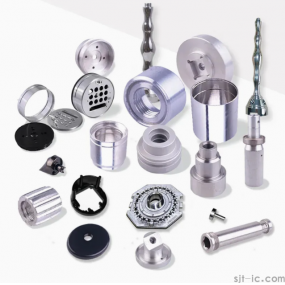
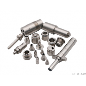
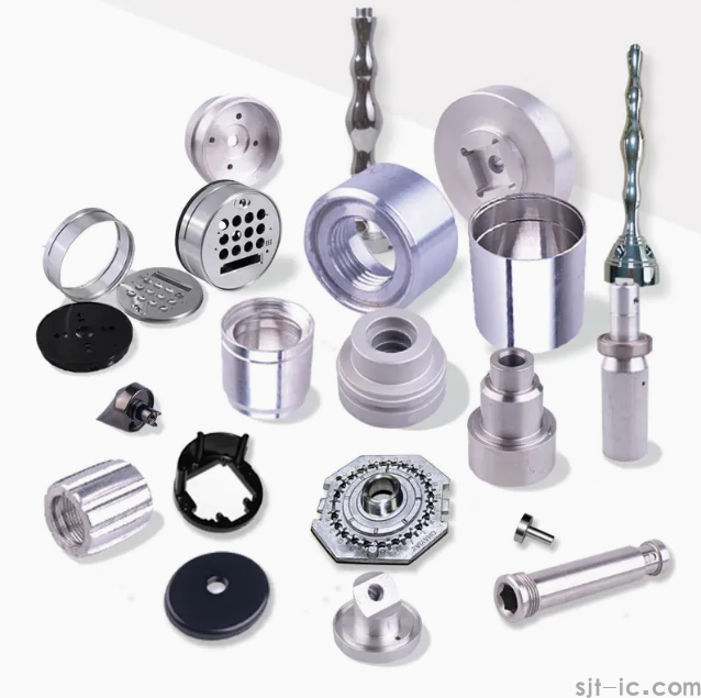
In the landscape of modern manufacturing, CNC Lathe Parts Processing stands as the cornerstone of precision engineering. From the aerospace sector’s demand for micron-level tolerances to the automotive industry's need for high-volume consistency, Computer Numerical Control (CNC) turning centers have revolutionized how raw materials—be it hardened steel, aluminum, brass, or advanced polymers—are transformed into complex cylindrical components. At EMAR, we recognize that understanding the intricate relationship between a machine’s architecture and its processing capabilities is vital for sourcing professionals and engineers. This guide delves deep into the anatomy of the CNC lathe, explores the full spectrum of machining operations, and highlights how leveraging advanced automation translates into superior part quality and cost efficiency for your supply chain.
The Foundation: What is CNC Lathe Parts Processing?
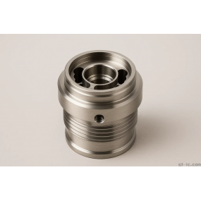
While the manual lathe traces its lineage back to ancient Egypt, today’s industrial demands require a quantum leap in automation and precision. CNC Lathe Parts Processing refers to the subtractive manufacturing method where a stationary cutting tool engages a rotating workpiece. Unlike manual labor dependent on handwheels and operator intuition, movement in a CNC lathe is dictated by coded instructions (G-code) fed to an onboard computer. This synergy of mechanical rigidity and digital control enables the production of parts with repeatable accuracy down to ±0.001mm, a feat unattainable in manual machining. The process encompasses both Internal Operations (ID) to modify inner diameters and External Operations (OD) to shape the exterior, all often achievable in a single setup.
Core Architecture: Key CNC Lathe Parts and Their Processing Roles
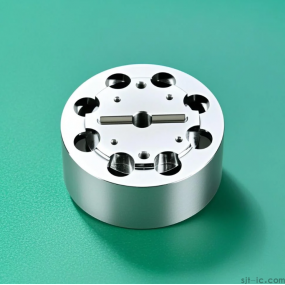
To optimize CNC Lathe Parts Processing, one must first understand the machinery's anatomy. Each component plays a specific role in maintaining the stability and precision required for high-tolerance work.
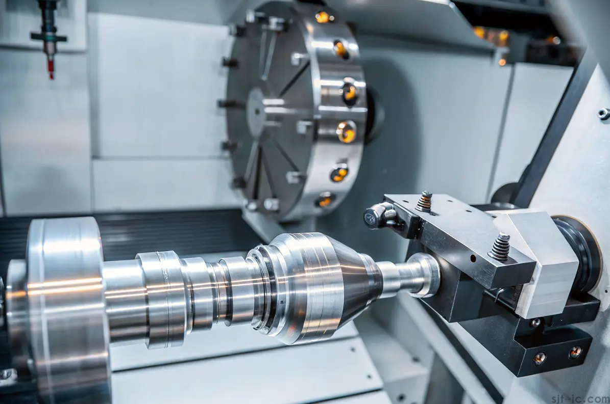
The Headstock and Main Spindle – The Powerhouse of Rotation
Positioned on the left side of the lathe bed, the headstock houses the drive motor and the main spindle. This assembly is the heart of the turning process, transmitting rotational force to the workpiece. The quality and rigidity of the main spindle directly correlate with surface finish and dimensional stability. The spindle nose secures the clamping mechanism, dictating the workpiece's concentricity during high-speed rotation. Modern headstocks offer variable spindle speeds, allowing EMAR operators to optimize cutting parameters for materials ranging from soft plastics to titanium alloys.
Clamping Precision: Chuck vs. Collet Systems
Secure workpiece holding is non-negotiable in CNC processing.
Chuck: Typically a 3-jaw (self-centering) or 4-jaw (independent) hydraulic or pneumatic device. The chuck is ideal for a broad range of diameters and irregular shapes, providing the robust grip necessary for heavy material removal.
Collet: Used for smaller diameter stock (typically up to 60mm). Collets offer a superior grip and higher concentricity than chucks, making them the preferred choice for high-precision micro-machining of small parts.
The Tailstock and Sub-Spindle – Stability and Automation
Situated opposite the headstock, the Tailstock provides critical reinforcement for long, slender workpieces like shafts or tubes. By engaging the workpiece center with hydraulic force, it mitigates deflection and vibration, ensuring consistency across the part's length. For advanced automation, many EMAR turning centers replace the tailstock with a Sub-Spindle. This secondary spindle grips the workpiece to perform back-side machining—allowing for part cut-off, drilling, and boring on the reverse face without manual intervention, a cornerstone of efficient, "lights-out" manufacturing.
The Carriage and Tooling Systems – Executing the Cut
The Carriage is the dynamic interface that facilitates movement. Comprised of the saddle and cross-slide, it rides along the lathe bed on precision-machined ways, moving the cutting tool along the X (vertical/depth) and Z (horizontal/length) axes. The tooling is housed in one of two primary configurations:
Turret Type: An indexing tool post capable of holding multiple tools. It rotates to bring the required drill, boring bar, or turning insert into position, enabling complex, multi-step CNC Lathe Parts Processing without manual tool changes.
Gang Type: Tools are mounted in a linear arrangement on the cross-slide. This allows for rapid indexing and is highly effective for high-speed production of small, simple components.
The Lathe Bed and Vertical Beam – Structural Integrity
The Lathe Bed is the cast, heat-treated foundation plate that supports the headstock, tailstock, and carriage. Its mass and rigidity absorb the immense forces and vibrations of machining, ensuring geometric accuracy over years of service. Some advanced designs incorporate a Vertical Beam configuration to minimize the accumulation of swarf (chips) on the guideways, a critical factor in maintaining long-term accuracy in automated environments.
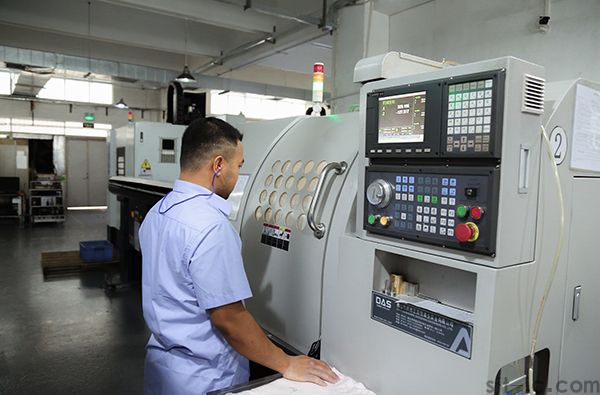
The CNC Control Panel – The Digital Brain
This is the command center for CNC Lathe Parts Processing. It interprets the 3D CAD model data and displays the tool path simulation. Operators use this interface to perform dry runs, adjust feed rates, and monitor spindle loads, ensuring the automated workflow executes with flawless precision.
Comprehensive Processes: Operations Performed in CNC Lathe Parts Processing
A CNC lathe is far more than a simple turning machine; it is a multi-functional platform capable of executing a wide range of operations, often eliminating the need for secondary equipment.
| Operation | Processing Description |
|---|---|
| Turning | Removal of large material volumes from the OD to reduce diameter. Ideal for roughing shafts. |
| Facing | Creating a flat, smooth surface on the end of the workpiece by moving the tool perpendicular to the axis. |
| Threading | Cutting precise external or internal threads (via tapping) of specific pitch and length. |
| Grooving/Parting | Cutting narrow channels or completely severing the finished part from the bar stock. |
| Drilling & Boring | Creating initial holes with a drill bit; Boring enlarges or finishes that hole to exact ID tolerances with steps or tapers. |
| Reaming | A finishing process performed after drilling to achieve a highly accurate diameter and mirror-like internal finish. |
| Knurling | Creating a textured pattern (serrated lines) on the surface for aesthetic grip or visual appeal. |
| Chamfering | Removing sharp burrs and creating beveled edges for safe handling and assembly. |
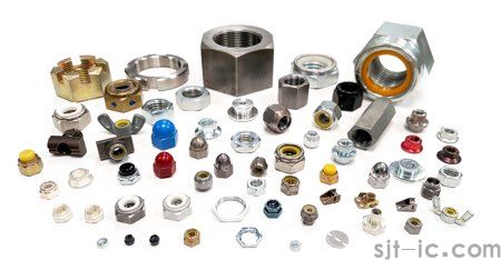
Applications and Industrial Versatility
The versatility of CNC Lathe Parts Processing makes it indispensable across a vast array of sectors. At EMAR, we service OEM customers and system integrators requiring components that vary in size from delicate surgical instruments to robust oil & gas fittings.
Aerospace: Precision components like landing gear pins, bushings, and engine discs requiring extreme tolerances and surface integrity.
Automotive: High-volume production of gears, shafts, pulleys, and brake rotors.
Medical: Complex geometries for bone screws, implants, and stainless-steel surgical tools.
Electronics & Hydraulics: Precision fittings, connectors, and valve bodies.
CNC Lathe vs. Manual Lathe: A Strategic Investment in Processing
For procurement managers evaluating cost-per-part, the distinction between CNC and manual processing is stark. While manual lathes offer flexibility for one-off repairs and prototypes (with setup times of 30-60 minutes), they are operator-dependent with tolerances often limited to ±0.01mm. CNC Lathe Parts Processing, by contrast, offers:
Repeatability: Identical parts produced over thousands of cycles without deviation.
Productivity: 3-5x faster for complex geometries, with the capability for 24/7 operation and single-operator oversight of multiple cells.
Labor Efficiency: Reduced per-unit labor cost and minimized material scrap through optimized toolpaths.
Advanced Capabilities: Multi-Axis CNC Lathe Processing
Beyond standard 2-axis turning (X and Z), EMAR leverages advanced multi-axis machines. 3-Axis, 4-Axis, and 5-Axis milling lathes incorporate Y-axis movement and live tooling. This allows for off-center drilling, milling of flats, and complex contouring on a turned part in a singular set-up. Even 9-Axis hybrid machines are deployed for extreme complexity, blending traditional turning with full 5-axis milling to eliminate cumulative fixture errors.
Conclusion
Optimizing your supply chain begins with understanding the capabilities of CNC Lathe Parts Processing. From the robust spindle to the micron-precision carriage, every component of the machine contributes to the final integrity of the machined part. At EMAR, we combine this advanced mechanical architecture with expert programming and automated workflows to deliver components that meet the most stringent global standards.
Are you looking to enhance the precision and consistency of your turned components? Contact the EMAR team today to discuss how our advanced CNC lathe solutions can streamline your production line and reduce your cost-per-part.
📞 Contact Phone: +86 18664342076
📧 Email: sales8@sjt-ic.com
🌐 Let’s turn your designs into reality with unmatched precision.